FreeCAD is an open source parametric CAD software, which is obviously also free. We’ve taken a quick look at it to check if it’s something that we’d recommend to other makers.
FreeCAD is still in heavy development (current latest non-dev. version is 0.15) and not finished. Keep this in mind when reading the rest of this post as much might be improved before full release. Many are however considering this as their CAD platform right now, so a quick look at the software in its current state might still be useful to many.
Overview
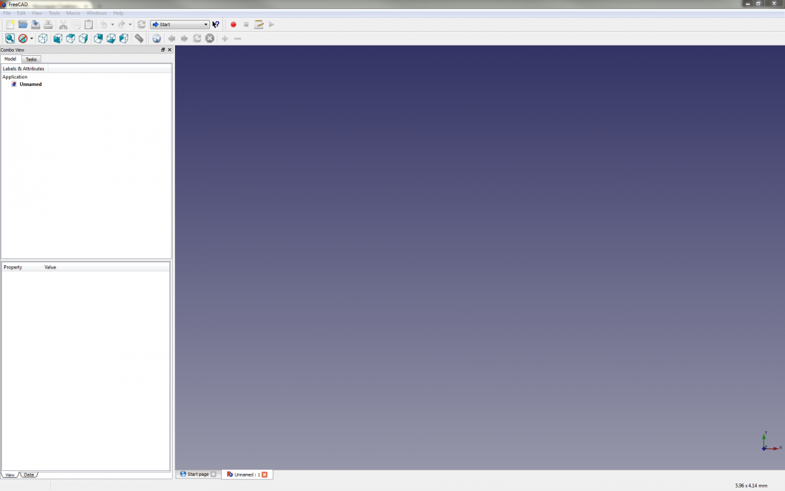
We are proponents of open source projects and we feel that these are very welcome to the CAD scene since a lot of CAD software is very expensive and/or always connected to some cloud or other online service. One issue with some open source projects is that they often sacrifice ease-of-use for functionality. FreeCAD has a problem with its ease-of-use, which most of this post will deal with.
FreeCAD has several so called workbenches which you switch between to do different tasks. Each workbench has its own toolbar. You have one workbench for sketching, one for modelling, one for rendering and so on. You also have more exotic ones as well such as ship design and robot movement. This might sound like a good idea, and this is highly subjective, but we prefer to at least have all modelling and sketch tools available at the same time and not have to switch between toolbars for accessing the different tools.
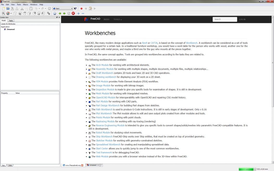
A positive aspect with this software is that it’s very customizable and that almost all of its features are accessible to Python. This way wou can definitely create some funky software or customize FreeCAD to your likings with some effort.
Our First Impression
Disclaimer: We’re aiming this post (and our blog in general) at makers and hobbyists, not necessarily at professionals. Thus we’ll consider and “judge” these kinds of programs as software for beginners and makers who don’t necessarily have PhDs. We think that these programs should be at least relatively easy to initially grasp since many are new to CAD and maybe want to model something for their new 3D printer or something along those lines. Many of our concerns may be trivial since we’re just not use to FreeCAD’s way of doing things, or we might just be plain stupid. Regardless, this post is our first impression of FreeCAD.
In FreeCAD the trend we’re experiencing is that it’s bloody difficult to do the most mundane tasks without reading the documentation.
We entered this quick look completely blind without reading much of the documentation first, just to see how we fared. And well, our first impression is not that good, unfortunately. It’s not necessarily that we think FreeCAD is very bad. Its learning curve is just a bit too steep in our opinion. Steep learning curves doesn’t have to be a dealbreaker, but we mean that software like this should have a certain level of intuitiveness, both for beginners and for more experienced people coming from other software platforms. At least for the most basic operations.
In FreeCAD the trend we’re experiencing is that it’s bloody difficult to do the most mundane tasks without reading the documentation. Tutorials we found within the software required version 0.16 while the newest non-dev. version is 0.15. The workflow seems really unintuitive and not at all streamlined, tools (and even commands such as new file and exit) get greyed out from time to time for no obvious reason (this is a feature, not a bug), ctrl+z (undo) often doesn’t do what you’d expect it to, the transform gizmo is in our opinion terrible, the sketching is cumbersome and the list goes on. On top of this we’re experiencing relatively frequent crashes.
A Few Examples
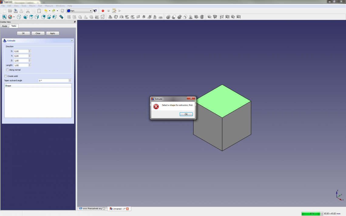
Let’s look at an example: creation of a simple box. When we press the create box primitive button we don’t get to choose the size, plane or position before it just pops up. Let’s say we want to extrude one of the sides to adjust the size. We open the Part workbench, select a face and press the extrude tool button. You can’t drag the face back and forth, but it seems like you must enter values in a sort of inspector window instead. You have to enter values for an XYZ direction vector as well as length and click apply. So we enter values that we think will extrude an XY face out along the Z-axis and click apply. An error message pops up that says Select a shape for extrusion, first. Hmmm… We had selected a face, hadn’t we? In the bottom of the inspector window it seems to be a list of shapes, but it’s empty. We have obviously left to get the grasp of some very fundamental concepts here. But the reality is at the time of writing that we, who have done a lot of CAD in the past, are not able to extrude a side of a cube without reading the documentation first. Should it be like this? We guess that’s a subjective matter.
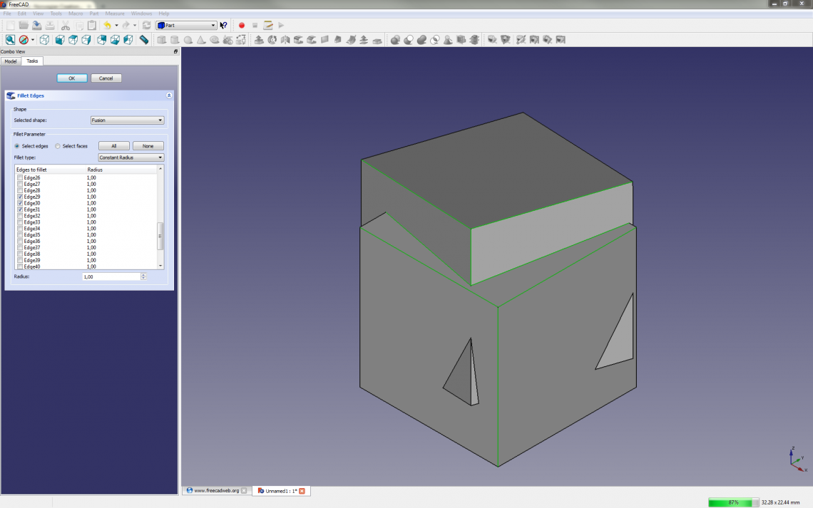
We love fillets and use it all the time. Let’s look at this tool as another example. To use the fillet tool you have to select a specific shape (aka. body) first and then select the edges you want to fillet. It seems like you’re not able to deselect edges without unchecking boxes in a list of generically named edges. This list can get loooong and you might not know which edge to uncheck. After you’re satisfied with the edge selection you enter the desired fillet radius before clicking ok. This is in our opinion super cumbersome as you can’t see what you’re doing in realtime by dragging a gizmo or something. Ctrl+z’ing just hides the whole shape. Then you explicitly have to unhide it again by selecting the shape in the inspector and choosing Visibility: true from a drop-down menu. In our opinion this isn’t a streamlined workflow, but it might be more effective ways to use this tool.
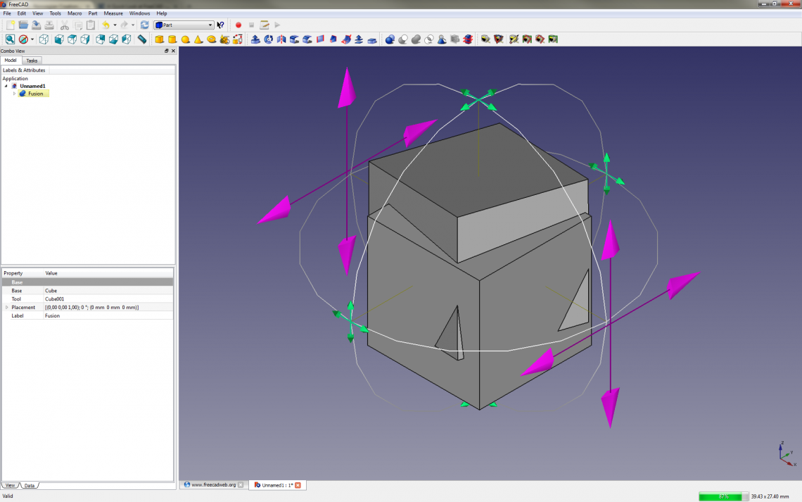
As a last example we’ll try to move and rotate a box. After finding the transformation tool a gizmo shows up. With this gizmo you can move the shape freely in one of three planes (shift-drag to lock single axis) or rotate the shape around one of three axes. There are no obvious ways to move an object a certain lenght along an axis, change pivot point or snap the shape to another entity. You can define a position relative to the origin as well as absolute rotation in the inspector window, but that’s not really sufficient i our opinion.
After playing around with different tools and workbenches there are so much that just doesn’t click, not just these examples. We’re left with this strange sour taste in our mouths after almost every tool test. Everything just feel so clunky and difficult to either use or understand in general.
Conclusion
We have a lot of experience with CAD software such as Fusion 360, 123D Design, Tinkercad, Sketchup and Onshape. While all of these aren’t super comparable to FreeCAD, they are all a lot more intuitive and easier to jump into than FreeCAD, and some of them doesn’t lack in features either. Similarly to FreeCAD they are all free as well (at least for makers and hobbyists).
The open source nature of this software is a good thing, though, and this is valuable to many. If you like to do CAD scripting or have the munchies for great customization, you’ll be able to satisfy your hunger here.
In its defense it’s still in relatively early development, and we’re sure that we’d be able to create something useful in FreeCAD if we invested the time to properly learn the software. FreeCAD veterans will probably be happy to argue against our impressions and show us the correct way of doing things. Regardless, that doesn’t change our first impression. Keep in mind that this is not a review, it’s just a first impression post. And our first impression compared to other CAD software we’ve tried before is not very good. This is mostly due to its low level of intuitiveness, its seemingly non-streamlined workflow and bugs.
Luckily it’s free, so you’re interested in this program despite reading this post you can just download it here and check it out for yourself! 🙂


