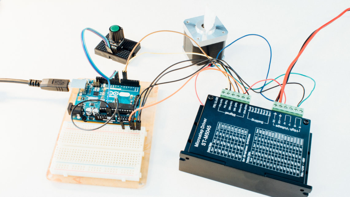
Not long ago, we published a blog post related to this topic. The difference is that the previous blog post used a rotary encoder to jog the stepper motor. This time we’ll swap out the rotary encoder with an ordinary potentiometer and use that to control either the position or speed of the stepper motor. We will use the code in the previously mentioned blog post as a base and do some alterations to achieve the desired behaviour. Just like last time, we aim towards using neither any libraries nor shields.

This blog post will mainly contain two code examples with some explanation. Both of these examples are actually untested, so feel free to report any bugs you find in the comment section below.
You should be aware of how potentiometers work prior to reading this post. We have written a blog post about this topic before, where we also look at firmware filtering, which can be useful in these kind of applications.
Position
Let’s look at how we can use the pot to control the stepper motor position.
Here we have two important parameters:
DRIVER_PULSE_PERIOD_USwhich sets the movement speed.STEPS_PER_ANALOG_VALUEwhich essentially sets the movement range.
This code doesn’t perform any calibration, but rather just assume that both the motor and the pot is centered at system start. The code also assume a 10-bit ADC (1024 analog values).
#define DRIVER_STEP_PIN   10
#define DRIVER_DIR_PIN    9
#define DRIVER_EN_PIN     8
#define POT_PIN           A0

#define DRIVER_PULSE_PERIOD_US  1600
#define STEPS_PER_ANALOG_VALUE  10

enum Driver_pulse_state_enum {PULSE_IDLE, PULSE_HIGH, PULSE_LOW};

unsigned long time_now = 0;
uint16_t driver_pulse_hold_time_us = DRIVER_PULSE_PERIOD_US/2;
uint8_t driver_pulse_state = PULSE_IDLE;
uint16_t target_pos = 512*STEPS_PER_ANALOG_VALUE;
uint16_t actual_pos = 512*STEPS_PER_ANALOG_VALUE;
int pos_error = 0;

void setup() {
	pinMode(DRIVER_STEP_PIN, OUTPUT);
	pinMode(DRIVER_DIR_PIN, OUTPUT);
	pinMode(DRIVER_EN_PIN, OUTPUT);

	digitalWrite(DRIVER_EN_PIN, HIGH);
}

void loop() {
	target_pos = analogRead(POT_PIN)*STEPS_PER_ANALOG_VALUE;
	pos_error = target_pos - actual_pos;

	if((pos_error) && (driver_pulse_state == PULSE_IDLE)){
		write_pulse_high();
	}

	if((micros() - time_now > driver_pulse_hold_time_us) && (driver_pulse_state == PULSE_LOW)){
		write_pulse_high();
	}

	if((micros() - time_now > driver_pulse_hold_time_us) && (driver_pulse_state == PULSE_HIGH)){
		write_pulse_low();
	}
}

void write_pulse_high(void){
	driver_pulse_state = PULSE_HIGH;

	if(pos_error > 0){
		digitalWrite(DRIVER_DIR_PIN, HIGH);
		actual_pos += 1;
	}
	else if(pos_error < 0){
		digitalWrite(DRIVER_DIR_PIN, LOW);
		actual_pos -= 1;
	}

	digitalWrite(DRIVER_STEP_PIN, HIGH);
		time_now = micros();
	}

void write_pulse_low(void){
	digitalWrite(DRIVER_STEP_PIN, LOW);
	time_now = micros();

	if(pos_error){
		driver_pulse_state = PULSE_LOW;
	}
	else{
		driver_pulse_state = PULSE_IDLE;
	}
}
This is essentially a P-controller where we find a difference (pos_error) between the actual position (actual_pos) and the target position (target_pos) and use this to control the motor.
Speed
This approach is a bit different. Here it is possible to run the motor an infinite amount either way. The pot controls how fast the motor runs and in which direction. When the pot is centered, the motor doesn’t move.
The three important parameters in this code are:
DEADZONEwhich sets the center pot range where the motor is idle.MIN_DRIVER_PULSE_PERIOD_USwhich sets the maximum speed.MAX_DRIVER_PULSE_PERIOD_USwhich sets the minimum speed.
#define DRIVER_STEP_PIN   10
#define DRIVER_DIR_PIN    9
#define DRIVER_EN_PIN     8
#define POT_PIN           A0

#define DEADZONE 50
#define MIN_DRIVER_PULSE_PERIOD_US  1000 //max speed
#define MAX_DRIVER_PULSE_PERIOD_US  3000 //min speed

enum Driver_pulse_state_enum {PULSE_IDLE, PULSE_HIGH, PULSE_LOW};

unsigned long time_now = 0;
uint16_t driver_pulse_hold_time_us = MIN_DRIVER_PULSE_PERIOD_US/2;
uint8_t driver_pulse_state = PULSE_IDLE;
int normalized_analog_value = 0;
uint8_t idle_flag = 1;

void setup() {
	pinMode(DRIVER_STEP_PIN, OUTPUT);
	pinMode(DRIVER_DIR_PIN, OUTPUT);
	pinMode(DRIVER_EN_PIN, OUTPUT);

	digitalWrite(DRIVER_EN_PIN, HIGH);
}

void loop() {
	normalized_analog_value = analogRead(POT_PIN) - 512;

	if(abs(normalized_analog_value)-DEADZONE < 0){
		idle_flag = 1;
	}
	else{
		idle_flag = 0;
	}

	driver_pulse_hold_time_us = map(abs(normalized_analog_value), DEADZONE, 512, MAX_DRIVER_PULSE_PERIOD_US, MIN_DRIVER_PULSE_PERIOD_US)/2;

	if(!idle_flag && driver_pulse_state == PULSE_IDLE){
		write_pulse_high();
	}

	if((micros() - time_now > driver_pulse_hold_time_us) && (driver_pulse_state == PULSE_LOW)){
		write_pulse_high();
	}

	if((micros() - time_now > driver_pulse_hold_time_us) && (driver_pulse_state == PULSE_HIGH)){
		write_pulse_low();
	}
}

void write_pulse_high(void){
	driver_pulse_state = PULSE_HIGH;

	if(normalized_analog_value > 0){
		digitalWrite(DRIVER_DIR_PIN, HIGH);
	}
	else if(normalized_analog_value < 0){
		digitalWrite(DRIVER_DIR_PIN, LOW);
	}

	digitalWrite(DRIVER_STEP_PIN, HIGH);
	time_now = micros();
}

void write_pulse_low(void){
	digitalWrite(DRIVER_STEP_PIN, LOW);
	time_now = micros();

	if(!idle_flag){
		driver_pulse_state = PULSE_LOW;
	}
	else{
		driver_pulse_state = PULSE_IDLE;
	}
}
Improvements and Conclusion
Low-pass filtering the analog signal is almost crucial in this type of setup, especially for the position control code. This can either be done in hardware or in firmware (e.g. using an exponential moving average filter). We still don’t have any form of acceleration in our motion control, so too high speed changes will result in losing steps.
The purpose of these code examples is to serve as inspiration for others who are making a project which involves controlling stepper motors. There are many ways of doing this, and you’d probably be better off using stepper control libraries and/or shields for safer, more robust and smoother movement and control.


